Modifying the Flyer for wind tunnel testing

When we originally built our wind tunnel replica, our engineering analysis showed that the structure would be sufficient to mount safely to a tripod mount. However, when we were granted an entry in the NASA Ames 40' x 80' wind tunnel, the facility strongly preferred a single point mount on a six-component strain gage balance. In order to accomidate those changes to our plan, we had to make several modifications to our replica, requiring nearly a complete rebuild.

The first issue to which we had to adapt was the new loadpath imposed on our aircraft by the new mounting scheme. When an airplane is in flight, the lift produced by the wings is offset by the force of gravity, and this force is spread out along the aircraft's wings, fuselage, engines, etc. When a model is being tested in a wind tunnel, while some of the lift is counteracted by gravity, most of the forces are concentrated around the support structure, which in this new case would be a single point underneath the center of the replica. Thus, the spars and ribs of the center section would have to react the full force of the lift of the airplane, which would be greater than the weight of the replica.

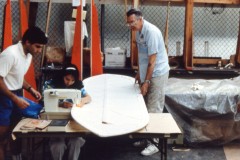
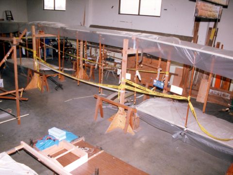
In order to accomplish this and to satisfy the NASA safety requirement of being able to safely tolerate loads three times higher than we expected, our structural analysis showed that we would have to replace the wooden spars in the lower center section with aluminum parts. Shown above is our aircraft with the section to be modified removed, and below are Rich Grimm and Marilyn Ramsey are carefully reattaching the aft ribs to the new aluminum spar. Once they are done, the front wooden spar will also be replaced.
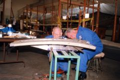


Normally, a six-component balance is hidden inside the fuselage of the airplane to be wind tunnel tested. Since the 1903 Flyer had no fuselage, we had to build a special pad that contained the balance and which would firmly support the replica.

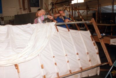
We also had to remove the previously installed mounting structure from the lower outboard section (see below). We also took this opportunity to run some instrumentation out to the wing tip.

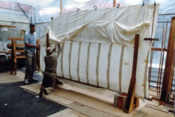
When we performed the structural test, we had an issue on the canard which required touching up the covering.


This was to be our mounting scheme. We buried strong steel pads inside the lower outboard sections that were to interface with the tripod mounting system we originally planned to use. Once this plan was changed, we needed to removed these pads from inside our aircraft.
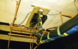
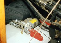
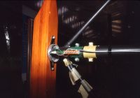
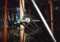
Some detail views of our instrumentation for the test. Above, the balance mounted underneath the replica, and the electric actuator we used to set the wing warping position hidden beside our Orville. Below are the tachometer and strain gages we used to determine the speed of the props and the torque being absorbed by the propshafts. The torque instrumentation fell behind schedule, and we wound up not being able to utilize it to take data.


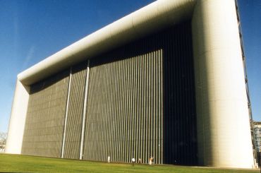
And this is where we would test. This is the inlet to the NASA Ames 80' x 120' wind tunnel, part of the same facility which houses the 40' x 80', where we actually tested. For scale, notice the people walking along the lower right of the inlet area.


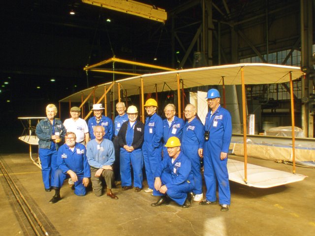
Hey NASA, we're here!

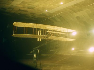
Installed and running. The slight streaks you might see in the photo aren't streaks or smudges at all. We have actually put pieces of yarns in the wind tunnel, tied to very thin wires. The reason for this is we want to be able to see what direction the wind is moving as it passes the Flyer. We also stiched some yarn tufts to our airplane (you can't seen them here) to look at the airflow much closer to the airplane as we pitch and yaw it out to various conditions we want to measure.

Copyright © 2003, AIAA Wright Flyer Project, all rights reserved.


Back to Main Page